Project Period: Jan 2012-June 2012( undergraduate project work which dealt with Controlling of an INDUCTION MOTOR )
The Simulink models developed can be found here.
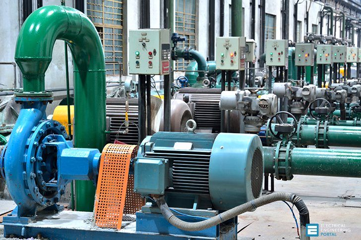
Induction motors are indispensable in our houses. It is being used in fans, water pumps, etc. It has a stationary part called a stator (where an electric supply is given) and a rotating part called the rotor. Operating on the principle of electromagnetic induction, it has a speed less than synchronous speed by an amount given by the slip of the motor. Synchronous speed is the speed of a revolving magnetic field. When a 3-phase supply is given to the stator of IM, the revolving magnetic field is produced and due to electromagnetic induction an EMF is induced in the rotor since the rotor conductors are short-circuited a current flows, and an effective torque is produced. So the rotor rotates at a rotor speed (Nr) that is less than the revolving magnetic speed (Ns) by slip speed. The rotor speed follows the stator speed to attain synchronous speed but cannot attain that due to the slip of the motor. For a single-phase motor revolving magnetic field is produced by phase-shifting devices like capacitors.
Ns = 120f/P s=Ns-Nr/Ns Nr=Ns (1-s)
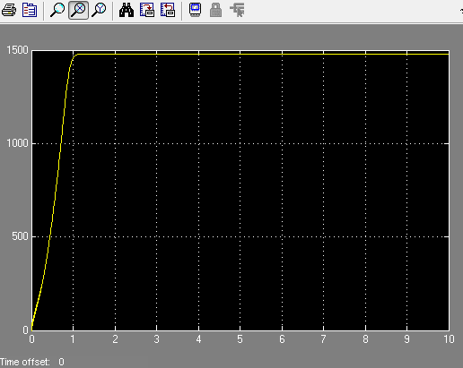
So a 4 pole motor fed at a frequency of 50Hz has a synchronous speed of 1500 rpm and if slip is 3% then has a rotor speed of 1455 rpm.
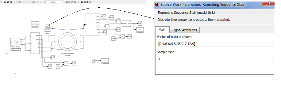
Now what if we require a temporary operation where the motor is to run at a speed of 1510. So from the discussion above it is clear that this is possible only by changing the synchronous speed. This can be done by
- By purchasing a new motor
- By using a frequency-shifting device
In the former method purchasing a new motor (minimum price of Rs 2000/- for 0.5 hp) that too for a temporary application proves to be uneconomical and useless. In the latter method speed variation in a wide range is only possible that is, even a unit increase in frequency (51Hz) would produce a speed of 1530 rpm. This is the point where our project proves to be useful. The speed can be varied above or below the synchronous speed according to our application with this circuit.
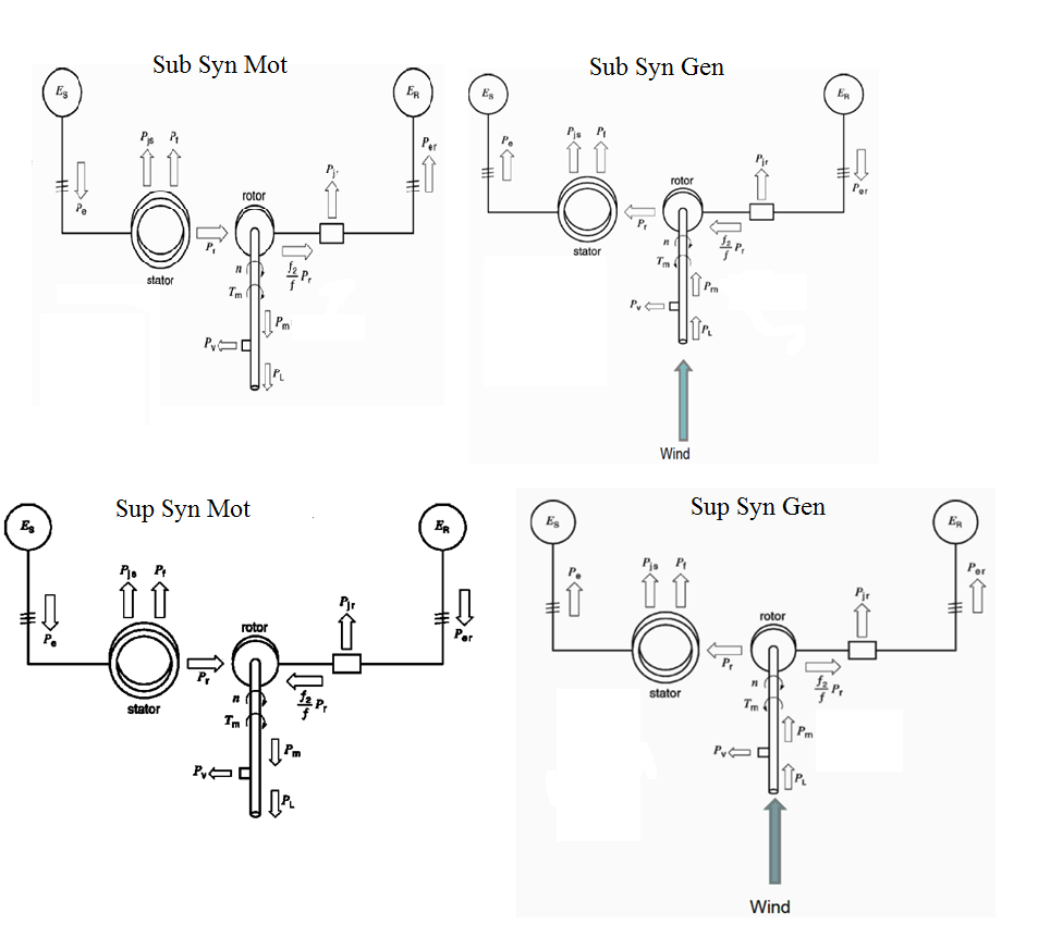
A slip ring induction motor has terminals in both the stator and rotor side and power can be given (motor) or taken (generator) from these terminals. In a normal induction motor due to a revolving magnetic field in the stator, a current and hence a power called slip power is produced in the rotor. This is a kind of power loss or power that is not utilized in normal induction operations. This power can be taken out from the rotor terminals (sub-synchronous operation). An equivalent slip power can be also fed to the rotor (super synchronous operation).
Now what happens if the rotor is fed with a slip power? Of course, the speed will go above synchronous speed. The motor rotates at a speed less than the synchronous speed due to the power fed to the stator and since extra power is fed to the rotor it rotates at a speed above synchronous and the speed above synchronous speed can be varied by varying power fed to the rotor. Even a speed of 1501 is possible by this method. This is called the super synchronous mode of motoring operation. Following is the fig.
The same idea is applicable in the case of induction generators. Normally for an induction machine to generate power it should be running at a speed greater than synchronous speed. If the prime mover with us cannot produce such a speed then generation is not possible. But if an external slip power is fed to the rotor in addition to the prime mover at a lower speed then generation is possible. This is called sub synchronous mode of generation operation. So with this circuit, the same machine can be made to operate at 4 modes. They are
- Sub synchronous motoring– power is fed to the stator and taken from the rotor
- Super synchronous motoring power is fed to the stator and rotor
- Sub sub-synchronous generation rotor is rotated at a speed less than the synchronous speed and power is fed to the rotor and taken from the stator
- Super synchronous generation- the rotor is rotated by an external force at a speed greater than synchronous speed and power is taken from the stator and rotor.
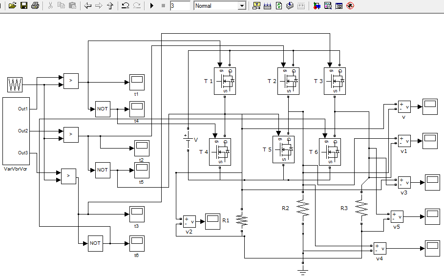
Normally the modes of operation were confined to sub-synchronous motoring and supersynchronous generation. Now coming to the experimental setup, a vector-controlled 3-level inverter-fed induction motor drive, is used to produce these 4 modes of operation in the same machine. As the name suggests the main component is a pulse width modulated 3Φ inverter controlled by vector control.
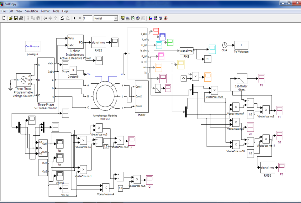
Since the whole setup is vast and practical experiments are uneconomical and time-consuming we used MATLAB. The motor with the same nameplate values is modeled. First, the open circuit test and blocked rotor test of the actual motor are done and characteristic values like rotor and stator resistance, inductance, etc are calculated. To provide more accuracy the load test of the motor modeled is done and compared with the load test values of the actual motor. The results proved to be matching. The load can be fed either in terms of speed or in terms of load torque
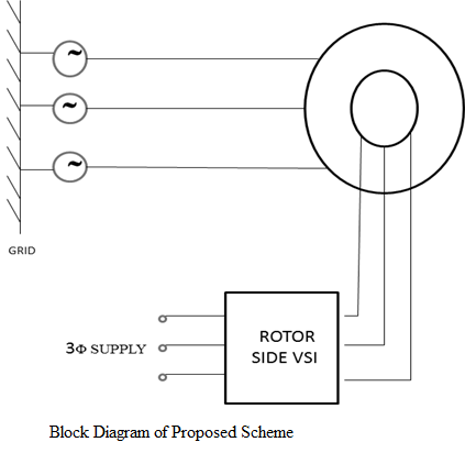
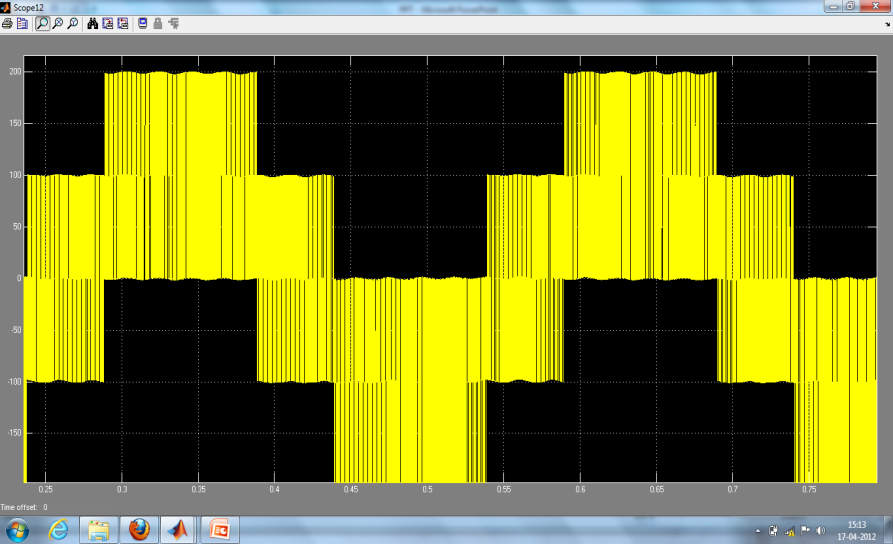
The input to the rotor is fed by the 3Φ inverter and controlled by pulse width modulation. So by effectively varying the pulse width, power fed can be controlled. To produce gate pulses for 3 phases a fixed frequency triangular wave is compared with 3 Φ sinusoidal signals which are at 120º phase difference. The frequency of sinusoidal signals should be at slip frequency as the rotor is at slip frequency(s*f).
This sinusoidal signal is produced by vector control. The stator input voltages which are at the abc reference frame of the stator(Vas, Vbs, Vcs) are first converted to the αβ reference frame of the stator (Vαs, Vβs) and this is converted to the dq reference frame( Vds, Vqs). Vqs will be zero since we have taken flux f along the d-axis. This is taken because the machine supplies electrical power to the grid during generating mode and this frequency should be the same as the grid frequency. This is multiplied by slip to get the dq rotor reference frame (Vdr, Vqr) which are dc quantities. The magnitude of Vdr and Vqr are taken to be equal. By changing the polarity of Vqr, generation and motoring operation is obtained. It should be converted back to αβ reference frame of the rotor (Vαr, Vβr) and then to abc reference frame of the rotor(Var, Vbr, Vcr) by reverse transformation and sinusoidal signal thus produced is compared with fixed frequency triangular wave. The frequency of the triangular wave should be at least 15 times that of the sinusoidal signal. Also, the magnitude of the sinusoidal signal should be less than that of the triangular wave to obtain a distortion-free output. According to the principle of PWM, the fundamental component of output will have the same shape and frequency as that of the reference signal. So output will be a pure sin wave as input and thus the harmonic profile can be improved. For all the above transformations, separate subsystems were formed.
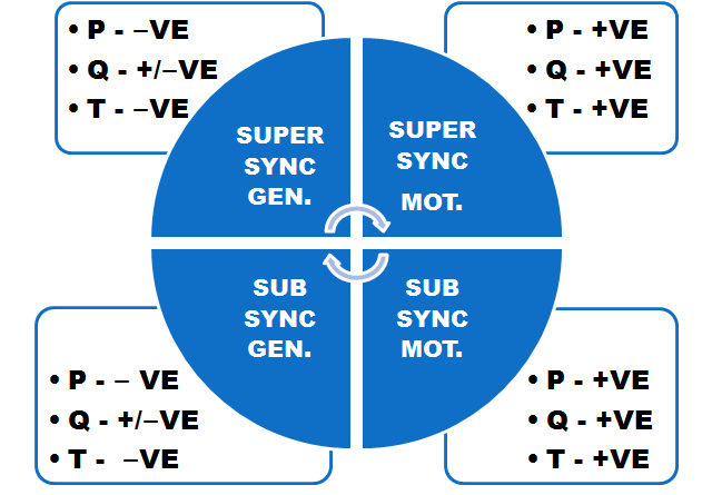
The 4 modes of operation can be obtained by reversing the polarities of slip (s) and Vdr. The polarity of the slip can be varied by varying the input speed. When
- s is positive and Vqr=Vdr mode is Sub Synchronous Motoring
- s is negative and Vqr =Vdr mode is Super Synchronous Motoring
- s is positive and Vqr= -Vdr mode is Sub Synchronous Generation
- s is negative and Vqr=-Vdr mode is Super Synchronous Generation
Reliable results were only attained in the motoring operation of a machine using an Induction Machine Block in SIMULINK. So to get generation mode we have modelled a machine using the generalized machine with all other controls.
OVERVIEW OF THE PROJECT
The whole project is divided into three parts:
1 Hardware Analysis- Actual Induction Motor
2 System Modelling using MATLAB
3 Voltage Source Inverter fed Vector Controlled Induction Motor drive
Hardware Analysis
No load and blocked rotor tests on a three-phase slip ring induction motor are conducted and the circuit parameters are determined. A load test is also conducted.
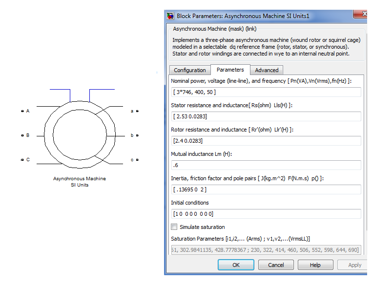
Rs | Xs | Rr | Xr |
| 2.53 | 0.0283 | 2.4 | 0.0283 |
System Modelling Using MATLAB
The system is modeled using parameters obtained and equations as in the figure below
The same tests(No load, blocked rotor, and load test) are conducted on the modeled machine.
No Load Model
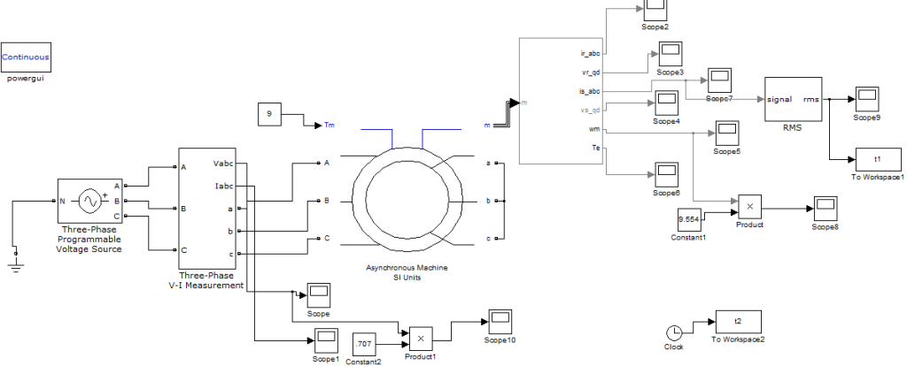

Load Model
The load can be fed either in terms of speed or in terms of load torque. Here torque is taken


Voltage Source Inverter Fed Induction Motor Drive
It can be divided into 4 sections as below
Pulse Width Modulation
Voltage Source Inverter
Vector Control
VSI Fed Vector Controlled Induction Motor
Pulse-width modulation (PWM), as it applies to motor control, is a way of delivering energy through a succession of pulses rather than a continuously varying (analog) signal. By increasing or decreasing pulse width, the controller regulates energy flow to the motor shaft. The motor’s own inductance acts like a filter, storing energy during the “on” cycle while releasing it at a rate corresponding to the input or reference signal. In other words, energy flows into the load not so much at the switching frequency, but at the reference frequency. The duty cycle of the output waveform needs to be modulated by a certain rule and as a result, both the output voltage and output frequency of the inverter can be regulated. The term duty cycle describes the proportion of ‘on’ time to the regular interval or ‘period’ of time; a low duty cycle corresponds to low power because the power is off for most of the time.
The index of modulation is
m=fp/fr
fp is the frequency of the carrying wave.
fr is the frequency of the reference.
The control factor in voltage is
r=Ar/Ap
Ar is the Amplitude of the reference.
Ap is the Amplitude of the carrying wave
Sinusoidal pulse width modulation
Among all PWM schemes, SPWM is one of the most popular and simple methods utilized in power inverter and motor control fields. Its main features can be summarized as sine-triangle wave comparison. A sine wave (modulated wave) is compared with a triangle wave (carrier wave) and when the instantaneous value of the triangle wave is less than that of the sine wave, the PWM output signal is at a high level . Otherwise, it is turned into the low level. The level-switching edge is produced at every moment the sine wave intersects the triangle wave. Thus the different crossing positions result in the variable duty cycle of the output waveform.
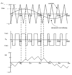

SPWM for Three-Phase VSI
This is an extension of the one introduced for single-phase VSIs. In this case, to produce 120⁰ out-of-phase load voltages, three modulating signals that are 120⁰ out of phase are used. FIG shows the ideal waveforms of three-phase VSI SPWM. To use a single carrier signal and preserve the features of the PWM technique, the normalized carrier frequency mf should be an odd multiple of 3. Thus, all phase voltages (VaN, VbN, and VcN ) are identical but 120⁰ out of phase without even harmonics; moreover, harmonics at frequencies a multiple of 3 are identical in amplitude and phase in all phases.
The main objective of static power converters is to produce an AC output waveform from a DC power supply. These are the types of waveforms required in adjustable speed drives (ASDs), uninterruptible power supplies (UPS), static variable compensators, active filters, flexible AC transmission systems (FACTS), and voltage compensators, which are only a few applications. For sinusoidal AC outputs, the magnitude, frequency, and phase should be controllable.


According to the type of AC output waveform, these topologies can be considered voltage source inverters (VSIs), where the independently controlled AC output is a voltage waveform. These structures are the most widely used because they naturally behave as voltage sources as required by many industrial applications, such as adjustable speed drives, which are the most popular applications of inverters. Similarly, these topologies can be found as current source inverters (CSIs), where the independently controlled AC output is a current waveform. These structures are still widely used in medium-voltage industrial applications, where high-quality voltage waveforms are required. Static power converters, specifically inverters, are constructed from power switches, and the AC output waveforms are therefore made up of discrete values. This leads to the generation of waveforms that feature fast transitions rather than smooth ones. For instance, the AC output voltage produced by the VSI of a standard ASD is a three-level waveform.

Although this waveform is not sinusoidal as expected its fundamental component behaves as such. This behavior should be ensured by a modulating technique that controls the amount of time and the sequence used to switch the power valves on and off. The modulating techniques most used are the carrier-based technique (e.g., sinusoidal pulse width modulation, SPWM), the space-vector (SV) technique, and the selective-harmonic-elimination (SHE) technique. The output voltage from an inverter can also be adjusted by exercising control within the inverter itself. The most efficient method of doing this is by pulse-width modulation control used within an inverter.
Induction motor speed control methods are varied in number of which vector or field oriented control is the most widely accepted method. The concept of vector control has opened up a new possibility that induction motors can be controlled to achieve dynamic performance as good as that of DC or brushless DC motors. The main advantage of vector control is to achieve good performance when speed and torque conditions change. Speed control is possible within the range of +/- 30%. To understand and analyze vector control, the dynamic model of the induction motor is necessary. It has been found that the dynamic model equations developed on a rotating reference frame make it easier to describe the characteristics of induction motors. The DC-like performance can be achieved in the AC machine if the machine control is considered in a synchronously rotating d-q reference frame. In the d-q model, the sinusoidal variables appear as DC quantities in a steady state, or the three current vectors and voltage vectors are transformed into equivalent current and voltage vectors in the d-q frame which is at 90°. The control is performed as in the DC machine.
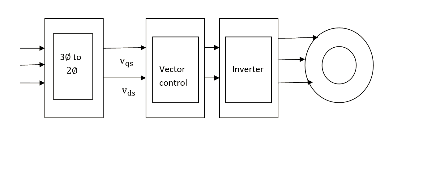
The voltage references are first transformed to the stationary coordinate system (usually through rotor d-q coordinates) and then fed into a modulator that using one of the many Pulse Width Modulation (PWM) algorithms defines the required pulse widths of the stator phase voltages and controls the transistors (usually IGBTs) of the inverter according to these. The number of voltage equations is reduced and the time-varying voltage equations become time-invariant ones which are advantages of reference frame transformation.
Based on the figure below the stator abc reference frame and rotor abc reference frame are transformed into their corresponding d-q reference frame.

Now for the purpose of feeding into PWM, the rotor side is reverse-transformed into the abc reference frame using the relation. For an Induction machine,
sVqs=Vqr
Vqr=Vdr
Reverse Rotor Transformations, reverse transformed rotor and the output are shown in fig


VSI Fed Vector Controlled Induction Motor
An induction motor can be operated in four different modes. Different control strategies can be opted on the stator and rotor side of a motor, here a vector control technique is implemented. Here a slip ring im is considered because its rotor side is free for control purposes. The four modes of operation are achieved by rotor side control. The conventional methods used for the control of speed and thereby operating the motor in different modes are static Kramer’s drive, dc link Scherbius drive, cyclo converter Scherbius drive, etc. In static Kramer’s drive, the slip frequency power from the rotor is converted to DC voltage which is then converted to line frequency and pumped back to the AC source. As the slip power can flow only in one direction, static Kramer drive offers speed control below synchronous speed only. This disadvantage of Kramer’s drive is overcome in the two configurations – dc link and cyclo converter Scherbius drives. They can be operated in sub-synchronous as well as super-synchronous modes.
Sub Synchronous Motoring
In this mode, the operation is similar to that obtained with a static Kramer drive. Slip and torque are both positive, therefore injected voltage must be in phase with the rotor current. Power flows into the stator and back out of the rotor circuit.


Sub Synchronous Generating
If generation below synchronous speed is required, torque must be negative whilst slip is positive. Again I2rRr + IrVi must be negative. Power is being injected into the rotor from the slip rings. If an induction motor is driven above synchronous speed, it becomes an induction generator and supplies energy to the power source rather than receiving energy. When a synchronous motor is over-driven, it becomes a generator, but it must still remain at synchronous speed.


Super Synchronous Motoring
Above synchronous speed, the slip is negative. For the torque to be positive,I2rRr + IrVimust be negative. Therefore, voltage and current must be out of phase with each other. Power is being injected into the rotor from the drive circuit connected to the slip rings, in addition to input power flowing into the stator.


Super Synchronous Generating
If generating above synchronous speed, slip and torque are both negative, therefore I2rRr + IrViis positive, and injected voltage is in phase with rotor current. In this case, mechanical input power is being supplied from the shaft and both the stator and rotor circuits are providing output power.

Reliable results were only attained in the motoring operation of a machine using an Induction Machine Block in SIMULINK. So to get generation mode, a machine using a generalized machine was modeled with all other controls as same.
Generalized machine theory
Rotating electrical machines work on the same basic principles. The various types differ from each other in their winding arrangements and the method of exciting these windings. The attempts to unify the piecemeal treatment of rotating electrical machines have led to generalized machine theory. In Generalized Machine Theory, any machine can be converted into a two-pole, two-winding machine. All types of electrical machines have certain common features as follows:
- An outer stationary member and an inner rotating member.
- Field windings and field poles, armature windings.
- An air gap between the stator and rotor.
- A common magnetic flux∅ crosses the air gap from one core to the other.
So a generalized approach is possible for representing different types of electrical machines.
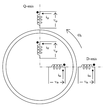
Two-Pole Representation Of a Machine
The distribution of current and flux under one pair of poles repeats itself under all other pairs of poles, whatever the actual number of pole pairs may be. Hence any machine can be replaced by an equivalent two-pole machine and the generalized machine theory is developed in terms of two-pole machines. The number of poles however may be introduced in determining the torque and speed of the machine. For two-pole machine representation,
- Each winding of the machine is represented by a single coil.
- The rotating windings are shown inside the circle and stationary armature windings outside the circle.
- The d-q axis is drawn perpendicular to each other, and the field windings are shown along the d-axis.
- The positive direction of the current in any coil is towards the coil in the lead nearer to the center of the diagram. The positive direction of flux is radially outwards along the axis of the coil.
- The positive direction of rotation of the rotor is taken as clockwise.
The dynamic equations are as follows and the machine is modeled using the same equation


Advantages, Future Scope, and Application
The main advantage of the proposed scheme is that the speed control is possible within +/- 30%. This is not possible in any other conventional scheme. Also the same IM is operated as a motor and as a generator. A modified form of SRIM–DFIG, is used for energy generation purposes.
- Large-capacity pumps and fan drives
- Variable-speed wind energy systems
- Shipboard VSCF (variable-speed/constant frequency) systems
- Variable speed hydro-pumps/generators
- Utility system flywheel energy storage systems
REFERENCE
1. T.J Miller “Theory Of Doubly Fed Induction Machine in Steady State” International Conference On Electric Machines-ICEM 2010 ROME
2. V T Ranganathan “Decoupled Control of Active And Reactive Power For A Grid Connected Doubly Fed Wound Rotor Induction Machine”, ieee Conference On Power Electronics And Drives 1999
3. R Krishnan “ Electric Motor Drives
4. Mohan Undeland and Robbins “Power Electronics: Converters Application and Design”
5. J B Guptha “Theory and performance Electrical Machines”.
6. P S Bhimbra “Generalised Machine Theory”
